combustion engineering
Example Systems
Standard Systems
Premix System
A typical premix system that we frequently supply for use on cement kilns all over the world consists of:
-
SS1 control unit (similar to the CU6 but with an integral 24Vdc power output to the premix unit).
-
CA170B premix unit.
-
J170PE torch made from mild steel tube and may be over 15 metres long.
-
LT cable to connect the control unit to the torch.
-
1/2″ hose to supply the air and gas mixture from the hose to the torch.
The system operates on bottled propane and compressed air to give a heat release of approximately 170,000 BTU/hr. The torch may be 15m long and so must be made in short sections for transportation. Once on-site, the sections are welded together.
Inspirated System
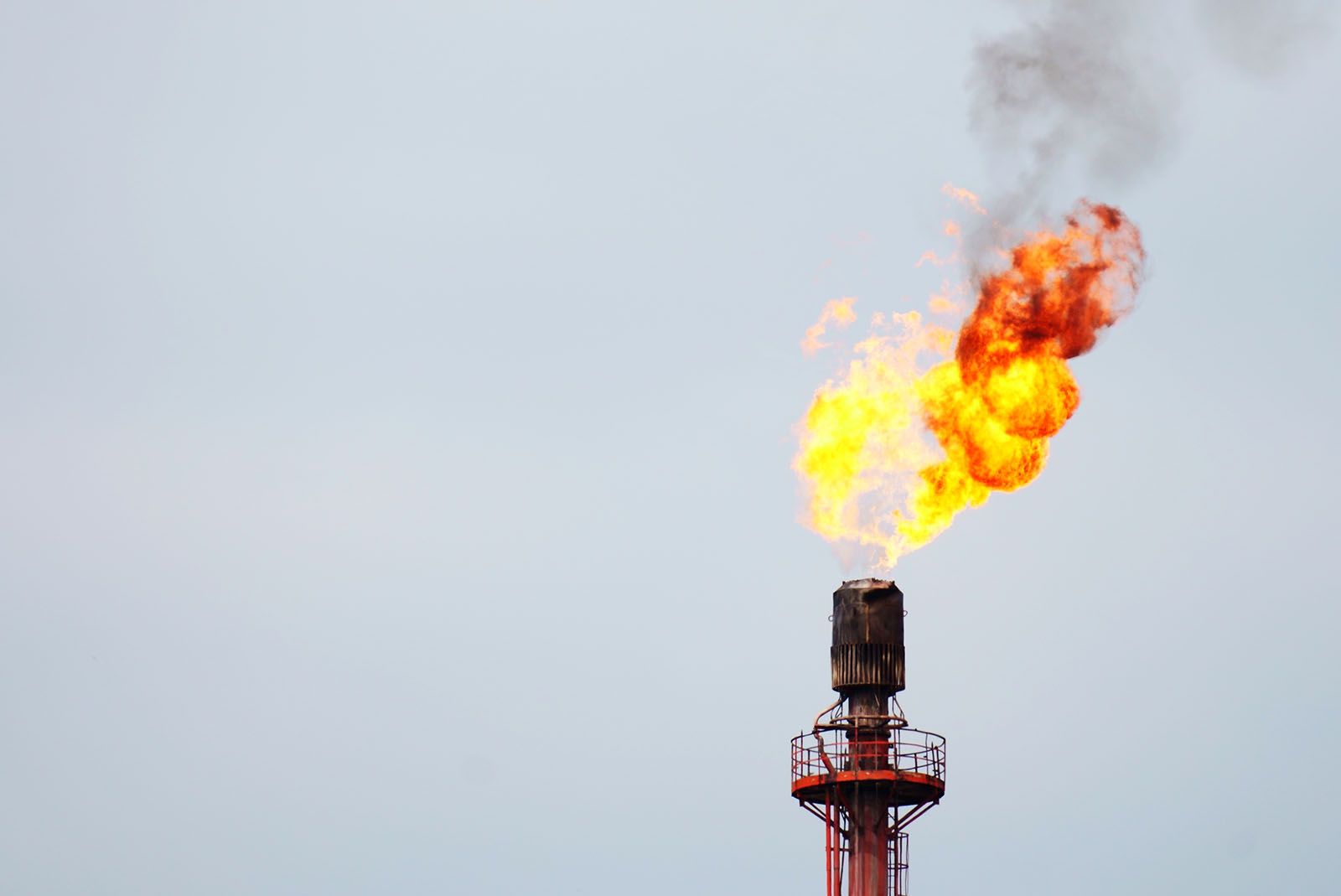
The following system is typical of the inspirated systems supplied to oil refineries. A system will consist of the following items:
-
CU7/3 in EExd enclosure.
-
J250 E torch with gas injector, including SA82 encapsulated coil.
-
Signal station with start pushbutton and status indication.
-
Interconnecting cables and glands.
This is an inspirated system that operates on natural gas or refinery gas. Air for combustion is taken from the atmosphere. The system has a heat release of approximately 100,000 BTU/hr. The signal station has a start pushbutton and a lamp to indicate that the torch is lit. The supply of gas to the torch is controlled by other equipment and so is not supplied by Igniters. Interconnecting cables between the control unit and signal station will be supplied to the length required
Spark-Only System
A typical spark-only system consists of:
-
SPG1A in an EExd enclosure
-
Encapsulated coil.
The encapsulated coil is fitted to the main installation and the SPG1A is located at a convenient place.
Bespoke Systems
When the requirements of a contract cannot be fully met by standard equipment, we will design a system to suit the application. The system is usually based on standard designs, which, with a few modifications, can be adapted to suit the application. The following are examples of a few recent bespoke systems.
- A customer needed a system to simultaneously ignite three burners with a single torch. The burners were close together forming a triangle and there was a single port in the centre of the triangle through which the torch is to be inserted. Our solution was to design a three-way burner head that fits onto a standard J250EI torch. The burner head was hand made from alloy 800HT and diverted the flame in three directions.
- A customer needed a mobile, battery-operated system. The solution was to design a trolley onto which three explosion-proof enclosures were mounted. The first enclosure housed a 12V sealed lead-acid battery, the second enclosure housed a 12V dc to 110V ac inverter, and the third enclosure housed a CU6/5 control unit. A gas control line was mounted onto the trolley and there was space for a 26Kg propane bottle and the torch. Provision was also made for the connection of a battery charger.
- A customer needed a portable spark-only system for use in a potentially explosive atmosphere. The solution was to design a carrier onto which two explosion-proof enclosures were mounted. The smaller of the two enclosures contained a 12 V sealed lead-acid battery and the larger enclosure contained a 12V dc spark generator. We also designed a spark-only torch based on the P78E, making it lightweight and easy to handle.
- A customer needed a system to ignite a pair of flare stacks that burnt off waste gas from an industrial process. The system was exposed to the elements on the coast and was located on the roof of a tall building. The system was also exposed to high temperatures from the flare stacks. Maintenance time was limited due to the second flare stack being in use whilst the first was being in overhauled, and vice-versa. Our solution was to locate a CU6 control inside the building well away from the elements. A premix unit, based on the CA170, was housed inside a stainless steel enclosure and installed close to the flare stack. A bespoke torch was designed. It was loosely based on a J250E torch. The torch was split into two parts; a base that was attached to the flare stack and the remainder was removable for maintenance away from the elements. The two sections were joined by a flange arrangement, with the conductor rod being joined by a sprung plunger. A flame elbow on the torch tip deflected the flame 90 degrees into the flare stack. An SA82 encapsulated coil was mounted onto the torch base.
- A customer needed two systems for use on process system. Each igniter system consisted of a CU7/3 control unit, J170E torch with retraction mechanism and premix unit. The two CU7/3 control units were housed in a single enclosure. Each J170E torch incorporated a thermocouple to monitor the temperature at its tip. The pneumatic retraction mechanisms were designed for the contract. The premix unit was mounted on top of the retraction mechanism with a sealing gland preventing any process gas from escaping to the atmosphere. A ball valve prevented the escape of process gas when the igniter was removed for maintenance.
